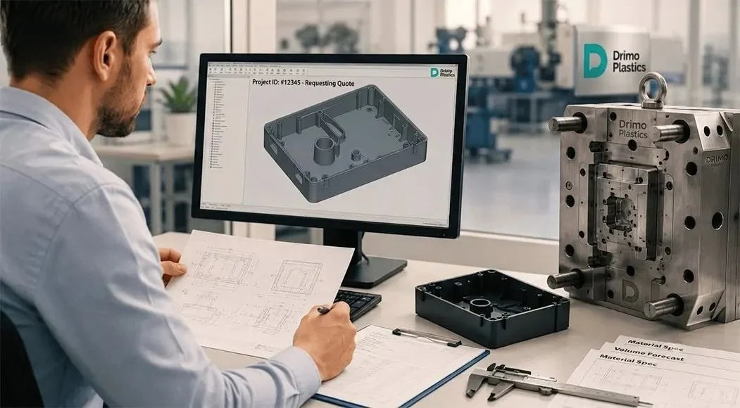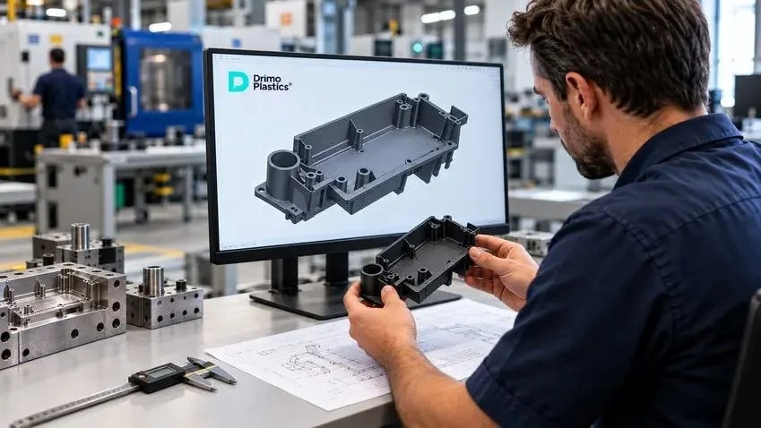
A part can look right in CAD and still present challenges in production. The 3D model defines its geometry, but injection molding adds other variables: resin flow, cooling and shrinkage, mold opening, and ejection.
That is why designing a functional product is not the same as designing one that can be manufactured consistently. Design for Manufacturing (DFM) connects geometry, material, mold, process, and quality requirements before committing to a significant tooling investment.
What Is DFM in Injection Molding?
DFM stands for Design for Manufacturing. In injection molding, it means evaluating and refining a part design so it works with the intended manufacturing process without adding unnecessary complexity or compromising the part’s function.
DFM does not replace product design or mold design. Product design defines function, dimensions, assembly, and appearance; DFM assesses manufacturability; and mold design turns that geometry into tooling capable of producing the part.
Why Review the Design Before Building the Mold?
A problem found in CAD usually leaves more options than the same issue discovered after the mold has already been machined.
An unplanned undercut, excessive material buildup, insufficient draft, or a difficult tolerance may later require changes to mold components or mechanisms already built.
An early review does not eliminate mold trials or guarantee that no adjustments will be needed. Its value is in resolving key decisions while there is still room to change geometry, material, tolerances, or the mold concept.
What Benefits Can DFM Bring to the Customer?
For a company that needs to move a plastic part into production, DFM offers more than improvements to the CAD model.
Better visibility into design risks. It highlights features that deserve attention before tooling: wall thicknesses, hard-to-fill areas, critical tolerances, or geometries that require additional mold mechanisms.
Better decisions about complexity and cost. An undercut, a texture, or a demanding tolerance may be fully justified. Understanding its impact before the mold is built makes it easier to evaluate the required solution with a clear view of the tradeoffs.
Avoiding costs that do not add functional value. Unnecessary material buildup tighter-than-needed precision, or avoidable mechanisms add demands to the mold, process, and inspection. The goal is not to make everything cheaper, but to distinguish where complexity adds value.
A more complete evaluation. When geometry, material, volume, assembly, and critical requirements are considered together, the manufacturer can work with fewer assumptions. At Drimo Plastics, our evaluation considers manufacturability, material, mold concept, quality, and design optimization.
Key Areas Reviewed in DFM for Injection Molding
Wall Thickness
Reasonably uniform wall thickness promotes more consistent cooling and shrinkage. A much thicker area concentrates material and increases susceptibility to sink marks or warpage; a wall that is too thin can make filling more difficult, especially over long flow paths.
There is no universal wall thickness. The appropriate value depends on the resin grade, geometry, flow path, part size, and function.
Draft Angles
A draft angle is a slight taper that helps the part release from the mold. If draft is insufficient, friction increases and the part may show marks or damage during ejection. The required angle depends on the material, depth, texture, finish, and geometry; there is no single value that applies to every part.
Radii and Transitions
Very sharp inside corners concentrate stress, while abrupt section changes create local differences in wall thickness. Appropriate radii and gradual transitions help address these issues, provided they do not create new areas of excessive material buildup.
Ribs and Bosses
Ribs add stiffness without increasing the thickness of the entire wall. Bosses are commonly used for screws, inserts, supports, or assembly features.
If too much material is concentrated at their base, cooling behavior changes and a sink mark may appear on the opposite surface. Their geometry should be evaluated together with the material, function, and finish requirements.
Undercuts
An undercut prevents the part from being removed with a straight mold opening and may require slides, lifters, or other mechanisms. It is not necessarily a design error: when the feature serves a necessary function, the solution should account for the additional complexity it introduces into the mold.
Parting Line, Gates, and Ejection
Part geometry influences where the mold separates, where resin enters the cavity, and how the part is ejected. Gate location affects the flow path; the parting line affects appearance and mold construction; and ejectors need areas that can accept force without deforming the part.
The customer does not need to design these elements, but it is important to define which surfaces are critical, visible, or sensitive to process marks.
How the Plastic Material Affects DFM
Material selection cannot be separated from geometry. Different polymers—and even different grades within the same resin family—vary in flow behavior, shrinkage, and stiffness.
A wall thickness that works well with one resin may be problematic with another. Fiber-reinforced or filled materials add orientation effects that influence properties and warpage. The more clearly the actual grade is defined, the fewer design decisions have to rely on assumptions.
Tolerances and Critical Dimensions
Not every dimension needs the same level of precision. A tolerance should correspond to a specific functional, assembly, safety, appearance, or interface requirement.
Critical to Quality (CTQ) characteristics are directly tied to function, assembly, safety, or another important product requirement. Identifying them helps focus control efforts where they matter most.
ISO 20457:2026 provides a framework for dimensional and geometric tolerances for molded plastic parts, taking into account factors such as shrinkage, geometry, and process conditions. It is not a universal tolerance table and does not replace project-specific evaluation.
How DFM Can Affect Mold and Production Costs
Many design decisions have an economic consequence. Geometry that supports a straightforward mold opening may avoid additional mechanisms; reducing unnecessary material buildup lowers material use and, in some cases, supports more efficient cooling; and limiting demanding tolerances to functionally necessary dimensions avoids adding unnecessary precision to tooling and inspection.
Sometimes the opposite is true: a more complex mold or a tight tolerance is fully justified by function, productivity, or quality requirements. The goal of DFM is not to achieve the cheapest possible mold, but to balance part performance, tooling investment, process stability, and production cost.
When Should a DFM Review Be Performed?
The best time is when the product requirements are defined well enough to evaluate the geometry, but before the mold design is committed.
Concept → CAD → DFM review → revisions → mold design → mold manufacturing → trials → validation → production.
The process is not always linear: trials may send the project back to the mold, the process, or the part design.
A review is also appropriate when the material, a critical characteristic, or an assembly requirement changes. When transferring plastic part production, the part, mold, resin, process, and acceptance criteria should be reviewed—not just the tooling moved.
What Information Helps Evaluate a Part?
The better the project context is defined, the more useful the evaluation will be. The most relevant information includes:
● 3D CAD file, preferably STEP/STP.
● 2D drawing with tolerances and critical dimensions, if available.
● Material or required material properties.
● Expected annual or total production volume.
● Application and operating conditions.
● Assembly method.
● Cosmetic and quality requirements.
In our guide on information needed to request an injection molding quote, we explain which details help start an evaluation, even when the project does not yet have complete documentation.
Common Issues to Identify Before Building the Mold
Some of the most common issues include:
● Abrupt wall-thickness changes or material buildup without a clear need.
● Insufficient draft.
● Undercuts discovered after the mold concept has already been defined.
● Very tight tolerances without a functional reason to justify them.
● Ribs or bosses that create local areas of excessive material.
● Changing the material after the geometry is essentially frozen.
● Failing to consider gates, the parting line, and ejection during part design.
These are not universal prohibitions. The risk comes from including them without first considering their manufacturing consequences.
DFM Checklist Before Moving Forward with the Mold
Before releasing a design for mold manufacturing, it is useful to ask:
● Are the wall thicknesses reasonably consistent for the material, function, and flow path?
● Are there areas of excessive material buildup or abrupt section changes?
● Do the surfaces have adequate draft?
● Are there undercuts, and is the proposed solution clear?
● Is the material defined with enough specificity?
● Are the most demanding tolerances justified by a real requirement?
● Have the CTQ characteristics been identified?
● Have the mold opening direction, parting line, gate location, and ejection been considered?
● Is it clear which surfaces are cosmetic and where process marks are acceptable?
If several of these questions are still unresolved, there are decisions to address before they become constraints built into the mold.
From Design to a Production-Ready Part
A production-ready part depends on more than a finished CAD model. The path connects requirements, material, manufacturability, mold design and manufacturing, trials, and validation.
Through our injection molding and mold manufacturing services, we evaluate projects based on the available technical information and the project’s manufacturing requirements.
For especially small parts, our article on micro injection molding goes deeper into material selection, CTQs, measurement, and manufacturability.
Frequently Asked Questions
What Does DFM Mean in Injection Molding?
It is the evaluation of a part design considering geometry, material, mold, process, and quality requirements.
When Should It Be Done?
During product development and before committing the mold; a new review is also appropriate when significant project requirements change.
What Problems Can DFM Help Identify?
Filling or ejection risks, problematic wall thicknesses, undercuts, difficult tolerances, and unnecessary mold complexity.
Can DFM Reduce Mold Cost?
It can help avoid unnecessary complexity or late modifications, but there is no universal percentage of savings.
What Does a Manufacturer Need to Begin Evaluating a Part?
A STEP/STP file is especially useful; a 2D drawing, material, volume, application, and critical requirements provide the rest of the context.
Does Changing the Material Require a Design Review?
It depends on the change, but its impact should be reviewed because flow behavior, shrinkage, stiffness, and reinforcement can affect earlier design decisions.